Intro
This is a resistor that essentially changes resistances based on the amount of light shining on it. From this you can do some voltage divider to get some voltage in relation to the max voltage and see that you get some voltage between the min and max voltage. This can correspond to some range to measure the amount of light shining on it.
Schematic
Selecting the Right Pull-Up Resistor
Check why we are pulling up and test pulling down
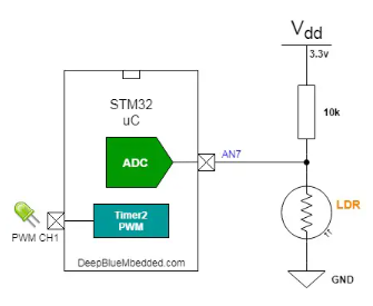
LDR have a changing resistance, relative the the amount of light. The Arduino can’t measure resistance, only voltage. So one way is to create a voltage divider. One resistor will be the LDR, the other one will be a fixed value resistor. To value of that resistor depends on the typical resistance of the LDR, the light-level range you’d like, power consumption, and other factors. With a higher value resistor, you get more precision in dark conditions.
LDRs themselves come in a considerable range of resistances. Search LDR specs and you will see what I mean. For example, from eBay I found one:
Bright Resistance(10Lux)(KΩ):20-230
Dark Resistance: 2 MΩ
This particular one, for example, seems to range from around 20k to 2M ohms. A reasonable series resistor would then seem to be somewhere in the middle of that range, otherwise all your readings would be skewed at one end of the scale.
For example, in this case if you used 10k and the LDR had 20 k resistance in very bright light, then the voltage would be 3.33 V
20000 / (20000 + 10000) * 5 = 3.33 V
Then if it got slightly darker and the LDR was 230 k, you would get:
230000 / (230000 + 10000) * 5 = 4.79 V
And if it was really dark you would get:
2000000 / (2000000 + 10000) * 5 = 4.98 V
You can see from those figures that you will never get a reading less than 3.33 V with this particular LDR and a 10k resistor. Thus a higher value resistor would give you a better range of readings.
However this totally depends on what resistance your particular LDR has.