Making your own ST-LINK V2 from STM32 Blue-Pill or STM32 Black-Pill
- Move the
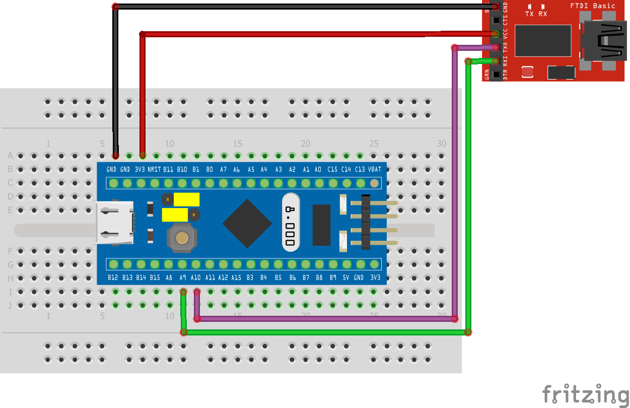
Boot0jumper from 0 to 1 - Connect the FTDI to the STM32 Board. Refer to Using Arduino as FTDI if you do not have the FTDI to perform this project. Also refer to your private OneDrive folder for all the resources used in this tutorial. Be careful to set adapter voltage to 3.3V!!!
- Flash the STM32F103C8T6 with the
STLinkV2.J16.S4.binfrom the folder.
Warning
The device you intend to flash must have at least 64Kb of flash memory. This means STM32F103C6T6A will not work since it has 32Kb of flash. Some ST-Link bootloaders are able to work on this but I am yet to figure out how to make them work!
- Now we disconnect everything and connect the board to computer with micro USB cable and also move the BOOT0 jumper back to 0. Use the
ST-LinkUpgrade.exetool to update the new ST-Link V2.
Warning
The ST-LinkUpgrade tool is an old one. Using a newer version of this will not work
- Connect to the new ST-Link using the STM32CubeProgrammer. Click on Firmware Update there. Keep unplugging and click refresh and update and it should pick it up.
- Now all we need to do is test it. I am testing it according to diagram below with another Blue Pill (don’t miss that short connection between PB12 and PB14!!!):

Tracing
- This has the added benefit of tracing directly without hurdles unlike the ST-Link v2 clones. With a little bit of research, you can see that the trace pin for the programmer is on PA10. Simply connect a jumper wire from the trace pin of the target (PB3 in the case of the bluepill) to PA10 on the new ST-Link and you should be able to trace.