This time, use the J-Link debugger. Go to this link and download the software and documentation required for the J-Link. Accept the terms of use and download.
Blinking LED
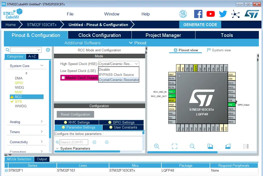
Regardless of the project you are doing you would always have to set the clock structure for the project.
- Click on the .ioc file in the root folder of the project
- Click on “System Core” on the left panel
- From the drop down click RCC
- Set high speed clock to Crystal/Ceramic Resonator
- Go to clock configuration on the top bar
- Set the system clock to be whatever you want
Warning
Always insert your code within the “User” comments or they would get wiped when you regenerate code from IOC
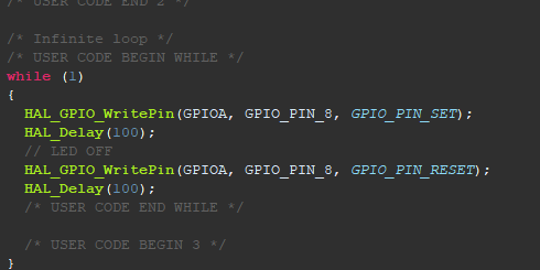
- It is kinda interesting that if you look at the schematic, the LED at PC13 is at an active low so that means you would have to set PC13 to low to turn on the LED.
Pulse Width Modulation (PWM)
Pulse Width Modulation (PWM) is a technique for generating a continuous HIGH/LOW alternating digital signal and programmatically controlling its pulse width and frequency. Certain loads like (LEDs, Motors, etc) will respond to the average voltage of the signal which gets higher as the PWM signal’s pulse width is increased. This technique is widely used in embedded systems to control LEDs brightness, motor speed, and other applications.
PWM Frequency
The PWM signal captures a few features. The first of which is the frequency, which is basically a measure of how fast the PWM signal keeps alternating between HIGH and LOW. The frequency is measured in Hz and it’s the inverse of the full period time interval. Here is how it looks graphically and its mathematical formula.

PWM Duty Cycle
The PWM’s duty cycle is the most important feature that we’re always interested in. It’s a measure of how long the PWM signal stays ON relative to the full PWM’s cycle period. The PWM’s duty cycle equation is as follows:

The duty cycle is usually expressed as a percentage (%) value because it’s a ratio between two-time quantities. And it directly affects the PWM’s total (average) voltage that most devices respond to. That’s why we typically change the duty cycle to control things like LED brightness, DC motor speed, etc.
PWM Resolution
The PWM resolution is expressed in (bits). It’s the number of bits that are used to represent the duty cycle value. It can be 8bits, 10, 12, or even 16bits. The PWM resolution can be as the number of discrete duty cycle levels between 0% and 100%. The higher the PWM resolution, the higher number of discrete levels over the entire range of the PWM’s duty cycle.
A PWM resolution of only 3 bits means there are only 8 discrete levels for the duty cycle over the entire range (from 0% up to 100%). On the other hand, a PWM with a resolution of 8 bits will have 256 discrete levels for the duty cycle over the entire range (from 0% up to 100%). You can use the interactive tool below to test this yourself.
Using GPS MODULE
https://controllerstech.com/gps-neo-6m-with-stm32/ add extern to the multiple declarations if &huart1
Using SoftSerial
https://github.com/liyanboy74/soft-uart HAL_TIM_Base_Start_IT(&htim1); is also important